

Onboard ship waste generation is not a new phenomenon. With HFO bunkers being used as fuel by the vast majority of seagoing vessels, heavy amounts of sludge and operational waste are unavoidable.
When operating at full service speed, a 150000 GRT Very large Crude Oil carrier can produce up to 0.8 metrics of sludge per day. Onboard sludge generation can account for up to 1% of total fuel consumption.
Accumulating this waste sludge until the ship arrives at the next port can be dangerous, unsanitary, and economically unfeasible for large storage tanks, reducing cargo capacity.
So, where should all of the waste from the ship go?
As a result, the incinerator on board the ship is a critical piece of machinery.
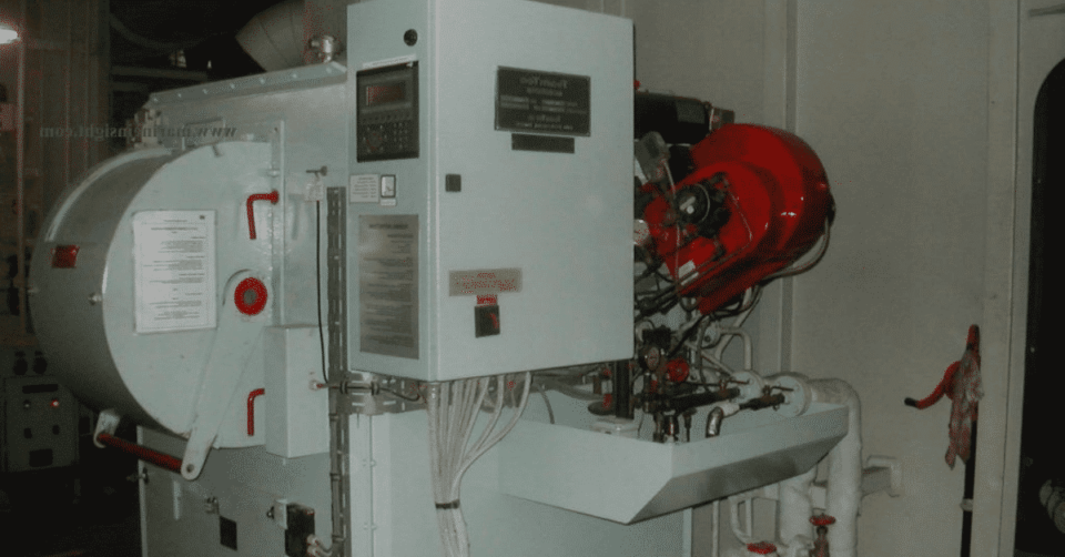
An incinerator, such as Atlas Incinerators, is a machine system in which we burn waste sludge from purifiers, Oily Rags, sometimes onboard waste paper, cardboard, waste oil generated in the engine room, and other operational wastes in accordance with MARPOL Annex VI, Regulation 16.
According to MARPOL Annex VI-Regulations 16.7 and 16.8:
1) All ships equipped with incinerators must have the manufacturer’s operating manual, which specifies how to operate the incinerator within its limits.
2) Operators must be trained and capable of following the guidelines outlined in the manufacturer’s operating manual.
As a result, understanding the significance of this machinery in the engine room is a requirement for all crew members. In addition, all Atlas Incinerators should be kept in good working order and as efficient as possible.
How to Keep the Incinerator Running at Full Capacity
Regular maintenance of combustion equipment is essential for achieving maximum efficiency from the incinerator. We’ll now look at how we can improve the incinerator’s efficiency by monitoring and operating each component.
Image Credit: sunflame.net
Rotary Cup Burner
The burner is at the heart of the combustion equipment, which also includes atomizing components, oil and air and driving components.
After each run, the atomizer cup of the main burner should be cleaned. The main burner’s air nozzle must be kept clear. Lubricant levels in the burner gearbox must be checked on a regular basis.
The supply pump relief valve setting can be used to adjust waste oil inlet pressure, whereas the flow of oil can be adjusted by controlling the flow control needle valve just before the burner or the recirculation valve (if fitted in the supply line).
A belt-driven rotary cup burner’s driving belt should be checked for wear or slackness on a regular basis. A worn belt can reduce the rotary cup’s driving rotational speed, affecting the fuel atomization pattern and resulting in incomplete combustion. The flame should be bright and yellow to the point where it cannot be seen with the naked eye.
Pilot Burner
The pilot burner, also known as the ignitor, is made up of an atomizer nozzle, a small fine filter, two electrodes and electrode plugs, and diesel oil piping. It provides the pilot flame in the form of a spark produced by an ignition transformer via electrodes, which ignites the main flame of the main burner.
To ensure a quick ignition, the pilot burner atomizer should be free of contaminants, and electrode distances should be as specified by the manufacturer. Otherwise, the pilot injection would be faulty, resulting in a misfire of the pilot flame.
In-line Filters
Every incinerator’s fuel supply line will contain a number of filters, most notably a duplex waste oil strainer and a Y-type strainer for its pilot ignitor burner. To avoid contaminants from clogging the fuel oil line and maintain flow, these filters should be cleaned and the air blown daily.
Furnace Air Damper Adjustment
The damper is used to manually adjust the air in the combustion chamber so that solid wastes can be burned. A large opening may help to strengthen the fire, but it may cause the chamber to take longer to heat up at first.
In certain incinerator models, this damper can also operate in automatic mode, diluting the combustion air in the furnace and controlling flue gas temperature. Secure the airflow for combustion and cooling, as well as a hot chamber and adequate ventilation, are required for substances to burn cleanly and with little smoke
Adjusting of Burner Air Damper (Wind Box Damper)
The main burner receives combustion air from the wind box wall via the damper located beneath the burner. Adjust it according to the oil feed rate to achieve good combustion with minimal smoke.
Exhaust Fan
Check that the exhaust fan is driven at a sufficient draught to maintain negative pressure in the combustion chamber and ensure proper exhaust gas circulation, as well as that gas does not blow out of the chamber while it is in operation.
The exhaust gas duct leading to the ship’s funnel should be free of obstructions; at times, pieces of cardboard fly off in the duct, obstructing gas passage and causing back pressure in the system.
Preparation of Water and Oil Tanks Prior to Incineration
Onboard sludge is a mixture of water and waste oil. Before burning waste oil tanks, it is critical to drain the layered water. This can be accomplished by evaporating the water content of waste oil tanks by heating them through steam coils. Heating waste oil makes it easier to transfer and atomize into fine fuel oil mist by burners.
For efficient combustion, the waste oil temperature at the burner inlet should be 90-100 degrees Celsius. Waste oil tanks must be cleaned on board at regular intervals (3-6 months per PMS) to remove solid wastes that accumulate in the tanks over time.
If you have a recirculation pump and a separate line, it is best to keep hot sludge recirculated at all times. Continuous oil agitation aids in better combustion.
Preparation of Solid Waste For Incineration
Incinerators frequently burn solid wastes such as sludge generated during main engine scavenge space inspections, stuffing box drain tank cleaning, scavenge drain tank cleaning, bilge tanks and waste oil tank cleaning, old engine system oils, general-purpose oily rags, and waste paper/cardboard. It is frequently preferable to separate large Sludge bags and cut them into smaller pieces for incineration.
Smaller charging lots improve combustion and prevent excess soot formation in the furnace.
Due to its lower combustibility and higher flashpoint, waste lube oil should not be burned all at once. Waste management should be planned in advance. Make sure the incinerator is not overcharged and that there is adequate ventilation.
Care For Furnace-wall (Refractory)
The incinerator’s combustion process takes place in the furnace. The furnace’s lining is made of refractory material, which traps heat and combustion gases inside the chamber. Damaged refractory exposes the bare metal casing, resulting in reduced heat transfer and inefficiency when operating the incinerator.
Temperature fluctuations in the furnace should be avoided to avoid refractory damage. Temperature changes can cause differential expansion between metal casings and refractory material, resulting in cracks and promoting corrosion. In the event of refractory damage, refractory patching up repair is required.
Flushing for the waste oil line with diesel oil before and after.
It is always a good practice to run the incinerator on diesel oil for the first 5 minutes, until the combustion temperature reaches around 650 degrees Celsius, and then switch to waste oil by switching the fuel supply valves and operating the change-over cock provided in the return line.
Similarly, before stopping, use diesel oil to flush the waste oil line to ensure that all lines are clear and free of contaminants.
These are some of the most important factors to consider when operating an incinerator for maximum performance and efficiency.